Audi's seem to have their calamities around 120-130,000, so anything that lives beyond this point, will probably have had a bit of work done and be sound enough. Personally, I still have a 145,000 mile A3 which has had a lot done and goes like a clock and previously, our A4 got killed at a junction with over 180,000.Dec. 30, 2014High mileage stories good or bad . | Audi-Sport.net
Monday, May 31, 2021
What is high mileage for a Audi?
2010 Mercedes Benz C 300 (204.054) V6-3.0L (272.947) Page 2997
Notes on CAN faults that cannot be read out as fault codes.Bus wake-up event
- An event that wakes up the bus without reason is designated a bus wake-up event.
- The cause of this is not the CAN networking, but the transmitter control unit or its sensors.
- Further possible causes of fault:
- Magnetic fields caused by nearby high-voltage installations, railroad installations or power plants.
- Magnetic fields can radiate on to lines and control units in rare cases and cause undefined behavior in the control units.
- The special tool 'Star Diagnosis CANtool' can be used to log bus wake-up events, bus keepawake events and other signals.
Bus keepawake event
- When a control unit keeps communication on the bus awake without reason, this is designated a bus keepawake event.
- The cause of this is not the CAN networking, but the transmitter control unit or its sensors.
- Further possible causes of fault:
- Magnetic fields caused by nearby high-voltage installations, railroad installations or power plants.
- Magnetic fields can radiate on to lines and control units in rare cases and cause undefined behavior in the control units.
- The special tool 'Star Diagnosis CANtool' can be used to log bus wake-up events, bus keepawake events and other signals.
1.1.2. No further information available.
1.1.3. General CAN fundamentals
Test 1.1.3.1: Low-Speed CAN (83,3 kBit/s)
Test 1.1.3.2: High-Speed CAN (125 kBit/s , 500 kBit/s)
1.1.3.1. Low-Speed CAN (83,3 kBit/s)
General CAN fundamentals
Low-Speed CAN (83,3 kBit/s)
- 83,3 kBit/s : For example:Interior CAN busSeries 211
- This CAN bus enables single-wire mode.
- 'Single-wire mode' means that fault-free communication between the control units is still possible even if one of the two CAN lines fails.
- This CAN bus does not require external terminating resistors.
Legend and description for figure 1CAN-H: CAN bus HighCAN-L: CAN bus LowECU 1 ... n: Control unit 1 ... nLegend and description for figure
2U 1: Specification approx. 3,6 voltsU 2: Specification approx. 0 voltsU 3: Specification approx. 2,5 voltsU 4: Specification approx. 1,4 voltsU 5:
Specification approx. 5 voltsContinue with button F2
2010 Cadillac Truck SRX AWD V6-3.0L Page 1697
2010 Cadillac Truck SRX AWD V6-3.0L Page 1697
Automatic Transmission Controls Schematics (See: Transmission and Drivetrain/Automatic Transmission/Transaxle/Diagrams/Electrical
Diagrams)
Connector End View Reference
Component Connector End Views (See: Diagrams/Connector Views/Connector End Views By Name)
Electrical Information Reference
* Circuit Testing (See: Testing and Inspection/Component Tests and General Diagnostics/General Electrical Diagnostic Procedures/Circuit
Testing/Circuit Testing)
* Connector Repairs (See: Testing and Inspection/Component Tests and General Diagnostics/General Electrical Diagnostic
Procedures/Connector Repairs/Connector Repairs)
* Testing for Intermittent Conditions and Poor Connections (See: Testing and Inspection/Component Tests and General Diagnostics/General
Electrical Diagnostic Procedures/Circuit Testing/Testing for Intermittent Conditions and Poor Connections)
* Wiring Repairs (See: Testing and Inspection/Component Tests and General Diagnostics/General Electrical Diagnostic Procedures/Wiring
Repairs/Wiring Repairs)
Description and Operation
Transmission Component and System Description (See: Transmission and Drivetrain/Automatic Transmission/Transaxle/Description and
Operation/AF40-6 - Automatic Transmission/Transmission Component and System Description)
DTC Type Reference
Powertrain Diagnostic Trouble Code (DTC) Type Definitions (See: Diagnostic Trouble Code Descriptions/Powertrain Diagnostic Trouble Code
(DTC) Type Definitions)
Scan Tool Reference
Control Module References (See: Testing and Inspection/Programming and Relearning) for scan tool information
Circuit/System Verification
1. Verify the transmission fluid level, color and odor is correct.
2. Operate the vehicle to induce a shift from fifth to sixth gear while observing the following scan tool parameters. The scan tool parameters has
to change the proper value referring to the current gear, compare the proper values with: transmission system description and operation. Refer
to Transmission System Description and Operation (M36 and MXE) (See: Transmission and Drivetrain/Automatic
Transmission/Transaxle/Description and Operation/AF40-6 - Automatic Transmission/Transmission System Description and Operation (M36
and MXE)). Perform this action 2 times.
* Clutch Pressure Control Solenoid Valve 1 Current
* Clutch Pressure Control Solenoid Valve 2 Current
* Clutch Pressure Control Solenoid Valve 3 Current
* Brake Band Pressure Control Solenoid Valve Current
* Shift Solenoid Valve 1
* Shift Solenoid Valve 2
瀚慖f the scan tool parameter does not change the proper value and no other DTCs than P0729, P0731, P0732, P0733, P0734, P0735, P0736,
P0780, P1731 is set, go to Circuit/System Testing.
瀚慖f any other DTC is set, diagnose that DTC first.
Circuit/System Testing
Dynamic Test
1. Perform the line pressure check. Refer to Line Pressure Check (See: Transmission and Drivetrain/Automatic
Transmission/Transaxle/Testing and Inspection/Symptom Related Diagnostic Procedures/AF40-6 - Automatic Transmission/Line Pressure
Check).
2. Perform the transmission fluid check. Refer to Transmission Fluid Level and Condition Check (See: Transmission and Drivetrain/Automatic
Transmission/Transaxle/Testing and Inspection/Symptom Related Diagnostic Procedures/AF40-6 - Automatic Transmission/Transmission
Fluid Level and Condition Check).
3. If all circuits test normal, replace the K71 Transmission Control Module. Verify the DTC does not reset.
瀚慖f the DTC resets replace the control valve body.
Repair Instructions
Perform the Diagnostic Repair Verification (See: Verification Tests) after completing the diagnostic procedure.
* Control valve body replacement-Refer to Control Valve Body Replacement (See: Transmission and Drivetrain/Automatic
Transmission/Transaxle/Valve Body/Service and Repair/AF40-6 - Automatic Transmission/Control Valve Body Replacement) for
replacement, setup, and programming.
* TCM-Refer to Control Module References (See: Testing and Inspection/Programming and Relearning) for replacement, setup, and
2018 Subaru WRX STI
Review, Pricing, and Specs
from Latest Content - Car and Driver https://ift.tt/2RcU4se
2018 Subaru WRX
Review, Pricing, and Specs
from Latest Content - Car and Driver https://ift.tt/3cpuKGX
2023 Kia Sportage to Officially Debut in July with a New Design
These first images of the new compact SUV confirm that it will look far more modern both inside and out.
from Latest Content - Car and Driver https://ift.tt/3paGIcC
2010 Cadillac Truck SRX FWD V6-3.0L Page 540
2010 Cadillac Truck SRX FWD V6-3.0L Page 540
Schematic Reference
Heated/Cooled Seat Schematics (See: Body and Frame/Seats/Seat Temperature Element/Diagrams/Electrical Diagrams)
Connector End View Reference
Component Connector End Views (See: Diagrams/Connector Views/Connector End Views By Name)
Description and Operation
Heated/Vented Seat Description and Operation (See: Body and Frame/Seats/Seat Temperature Element/Description and Operation/Heated/Vented
Seat)
Electrical Information Reference
* Circuit Testing (See: Testing and Inspection/Component Tests and General Diagnostics/General Electrical Diagnostic Procedures/Circuit
Testing/Circuit Testing)
* Connector Repairs (See: Testing and Inspection/Component Tests and General Diagnostics/General Electrical Diagnostic
Procedures/Connector Repairs/Connector Repairs)
* Testing for Intermittent Conditions and Poor Connections (See: Testing and Inspection/Component Tests and General Diagnostics/General
Electrical Diagnostic Procedures/Circuit Testing/Testing for Intermittent Conditions and Poor Connections)
* Wiring Repairs (See: Testing and Inspection/Component Tests and General Diagnostics/General Electrical Diagnostic Procedures/Wiring
Repairs/Wiring Repairs)
Scan Tool Reference
Control Module References (See: Testing and Inspection/Programming and Relearning) for scan tool information
Circuit/System Testing
B2425 0B, B2425 0D, or B2425 0E
1. Ignition OFF, disconnect the X4 harness connector at the K40 seat memory control module.
2. Ignition ON, verify that a test lamp illuminates between the B+ circuit terminal 5 and ground.
瀚慖f the test lamp does not illuminate, test the B+ circuit for a short to ground or an open/high resistance.
3. Ignition OFF, connect the X4 harness connector at the K40 seat memory control module and disconnect the harness connector at the E14A
seat back heating element.
Note: Element resistance must be measured twice to ensure that all failure conditions are simulated. First with the seat unoccupied, then with
the seat occupied.
4. Test for 0.5 - 5 Ohms between terminal A and terminal B.
瀚慖f not within the specified range, replace the E14A seat back heating element.
5. Connect the harness connector at the E14A seat back heating element and disconnect the X3 harness connector at the K40 seat memory
control module.
Note: Element resistance must be measured twice to ensure that all failure conditions are simulated. First with the seat unoccupied, then with
the seat occupied.
6. Test for 1 - 7 Ohms between control circuit terminal 11 and control circuit terminal 6.
瀚慖f less than the specified range, test for a short between the control circuits. If the circuits test normal, replace the E14B seat cushion
heating element.
瀚慖f greater than the specified range, test the control circuits for an open/high resistance. If the circuits test normal, replace the E14B seat
cushion heating element.
7. If all circuits test normal, replace the K40 seat memory control module.
B2430 0B, B2430 0D, or B2430 0E
1. Ignition OFF, disconnect the X4 harness connector at the K40 seat memory control module.
2. Ignition ON, verify that a test lamp illuminates between the B+ circuit terminal 5 and ground.
瀚慖f the test lamp does not illuminate, test the B+ circuit for a short to ground or an open/high resistance.
3. Ignition OFF, connect the X4 harness connector at the K40 seat memory control module and disconnect the harness connector at the E14C
seat back heating element.
Note: Element resistance must be measured twice to ensure that all failure conditions are simulated. First with the seat unoccupied, then with
NISMO Will Restore Your Classic Nissan Skyline to Like New—for More Than $400,000
Nissan seems to understand the importance of preserving important Skyline models, like the R32-generation one seen here, before it's too late. That's why the company recently launched a restoration program through its NISMO division and first spotted by Japanese Nostalgic Car, which is extensive. Extensive enough to justify the cost, which is a few hundred thousand dollars? Let's take a closer look and see.
Remember, not too long ago Nissan announced it was putting some hard-to-find parts for R32 Skyline GT-Rs back into production. And the prices of Skyline GT-Rs are hitting new heights, too. This seems like the next logical step, producing like-new versions of classic Skylines replete with special build plates and an impeccable pedigree, for a suitable sum. And it's not too dissimilar from Honda's NSX Refresh Plan in Japan—leveraging the company's incomparable expertise to make the end result as correct as it could possibly be. While that program may eventually come to America, it doesn't seem like Nissan's will. That said, any American owner with the kind of scratch to afford a restoration like this could probably afford to ship a car to Japan and back.
NISMO begins the process by examining the car. It must be a suitable candidate, or it can't receive the highest level of restoration. The customer then decides if they want to restore it back to original shape, or to change the specification—if it's possible, you could change to a trim like V-Spec, although the VIN would still indicate the original specification. The car is then completely disassembled, inspected, and—if necessary—the frame is carefully returned to spec. Any body panels that need repair are fixed or replaced. After that, the body is taken down the the bare metal and then dipped in an electroplating bath for corrosion protection, and the body and any parts that need a coating are painted—and again, there's an opportunity for the owner to choose the original color or repaint it in a different shade.
Meanwhile, the engine is is fully disassembled and essentially remanufactured. All wear parts are replaced, and everything else is machined or corrected as necessary. If the owner wants, NISMO can reassemble the engine in a higher state of tune, too. The engine then heads to a dyno for a check-up, and the full driveline is similarly disassembled and remanufactured as necessary.
While all that is fairly standard full restoration stuff, the level of detail beyond that is unreal. All the electronics are inspected and, if necessary, replaced. The original wiring harness is reused but any degraded connectors are redone. Once the entire car is put back together, an extensive test drive program is run with a NISMO test driver, to make sure it performs as expected, and also that there are no rattles, squeaks, or unusual vibrations.
But if you were hoping that NISMO would recover the interior in original fabrics and leathers, you're out of luck. Due to modern fire retardant requirements, NISMO can't legally refinish the interior in OE materials. An owner can either ask for the innards to be cleaned as much as possible, or they can work with the company to use fabrics from modern R35 GT-Rs. Presumably a third-party shop could install NOS interior materials if you could source them, but NISMO won't. It's a minor (and understandable) downside to the otherwise extensive restoration.
"At today's exchange rates, the full ""Restored by NISMO"" treatment will set you back about $432,000. There are lower levels of restoration at lower prices. But given the end product—as you can see in the gallery—for the right buyer, this might be worth it. At a minimum, Nismo now has the experience (and rare parts back in production) to restore the most important Skylines out there—and whatever the price, that's going to be important to preserve the company's heritage."
2010 Mercedes Benz C 300 (204.054) V6-3.0L (272.947) Page 2773
1.3.2.1.9. Check power supply at control unit N93 (Central gateway control unit).
1.3.2.1.9. No further information available.
If the fault code is not current, it may be deleted. In this case, the battery voltage was too low over an extended period.Charge the battery, if
necessary.Note:This fault could result in consequential faults. You should therefore process this fault first and then erase the fault
memory.Question:Is the fault current in several control modules?
YES
Possible cause and remedy
- Battery voltage too low.Test battery.Charge battery, replace if necessary.
- If fault occurs again:Check alternator.Communication with ECU required
- The quiescent current is too high.Test quiescent current.
NO
Test prerequisite
- Fuse o.k.
- Fuse o.k.
Test sequence
- Ignition: OFF
- Measurement at component
- Measure direct voltage with multimeter between ground socket and socket
Specified value
- Voltage[11.0...14.5] V
Question
- Is the measurement value OK?
2010 Cadillac Truck SRX FWD V6-3.0L Page 639
2010 Cadillac Truck SRX FWD V6-3.0L Page 639
瀚慖f less than the specified range, test either control circuit for a short to ground. If the circuits test normal, replace the X53 fuse block-rear.
瀚慖f greater than the specified range, test either control circuit for a short to voltage or an open/high resistance. If the circuits test normal,
replace the X53 fuse block-rear.
11. If all circuits test normal, replace the K9 BCM.
Component Testing
1. Ignition OFF, disconnect the harness connector at the appropriate A23 door latch assembly.
2. Install a 25 A fused jumper wire between one of the control terminals and 12 V. Momentarily install a jumper wire between the other control
terminal and ground. Reverse the jumper wires at least two times, the A23 door latch assembly should perform the LOCK and UNLOCK
functions.
瀚慖f it does not perform as specified, replace the A23 door latch assembly.
Repair Instructions
Perform the Diagnostic Repair Verification (See: Verification Tests) after completing the diagnostic procedure.
* Front Side Door Lock Replacement (See: Body and Frame/Locks/Door Locks/Service and Repair/Front Side Door Lock Replacement)
* Rear Side Door Lock Replacement (See: Body and Frame/Locks/Door Locks/Service and Repair/Rear Side Door Lock Replacement)
* Fuse Block Replacement (See: Maintenance/Fuses and Circuit Breakers/Fuse Block/Service and Repair/Removal and Replacement/Fuse
Block Replacement)
* Control Module References (See: Testing and Inspection/Programming and Relearning) for BCM replacement, setup, and programming
B3135
DTC B3125, B3130, or B3135
Diagnostic Instructions
* Perform the Diagnostic System Check - Vehicle (See: Testing and Inspection/Initial Inspection and Diagnostic Overview/Diagnostic System
Check - Vehicle) prior to using this diagnostic procedure.
* Review Strategy Based Diagnosis (See: Testing and Inspection/Initial Inspection and Diagnostic Overview/Strategy Based Diagnosis) for an
overview of the diagnostic approach.
* Diagnostic Procedure Instructions (See: Testing and Inspection/Initial Inspection and Diagnostic Overview/Diagnostic Procedure
Instructions) provides an overview of each diagnostic category.
DTC Descriptors
DTC B3125 01
- Driver Door Only Unlock Circuit Short to Battery
DTC B3125 02
- Driver Door Only Unlock Circuit Short to Ground
DTC B3130 01
- All Doors Unlock Circuit Short to Battery
DTC B3130 02
- All Doors Unlock Circuit Short to Ground
DTC B3135 01
- All Doors Lock Circuit Short to Battery
DTC B3135 02
- All Doors Lock Circuit Short to Ground
Diagnostic Fault Information
2018 Subaru Legacy
Review, Pricing, and Specs
from Latest Content - Car and Driver https://ift.tt/3uCWi1I
2018 Subaru Impreza
Review, Pricing, and Specs
from Latest Content - Car and Driver https://ift.tt/2RagbQ0
Audi shows us its concept for luxurious charging lounges of the future
Filed under: Green,Audi,Green Culture,Technology,Electric,Infrastructure

Continue reading Audi shows us its concept for luxurious charging lounges of the future
Audi shows us its concept for luxurious charging lounges of the future originally appeared on Autoblog on Mon, 31 May 2021 11:00:00 EDT. Please see our terms for use of feeds.
Permalink | Email this | CommentsJoin Car-Loving Comedy Writer and Podcast Host Spike Feresten on the Next Episode of Inside Track
On June 9, Road & Track will talk with Spike about his career writing for comedy greats and his passion for cars.
from Latest Content - Car and Driver https://ift.tt/2SMgoJp
起亚EV6仅3.5秒“破百”,以高性能电动车正式出道
起亚EV6仅3.5秒“破百”,以高性能电动车正式出道
自从3月30日,起亚在全球正式发布全新的EV6纯电跨界车之后,不出所料该车与其兄弟车现代Ioniq 5一样,收获了众多消费者的热情追捧。
Does Toyota Aygo have sat nav?
Does Toyota Aygo have sat nav?
Every Aygo has Toyota's 7.0in the touchscreen infotainment system, which includes Bluetooth and a DAB radio (with four speakers). There's no option of adding a built-in sat-nav, but the system includes Apple CarPlay and Android Auto smartphone integration, which lets you use your phone's navigation apps. Toyota Aygo Interior, Sat Nav, Dashboard | What Car?
Junkyard Gem: 1984 Subaru DL Hardtop Coupe
Filed under: Subaru,Automotive History,Coupe
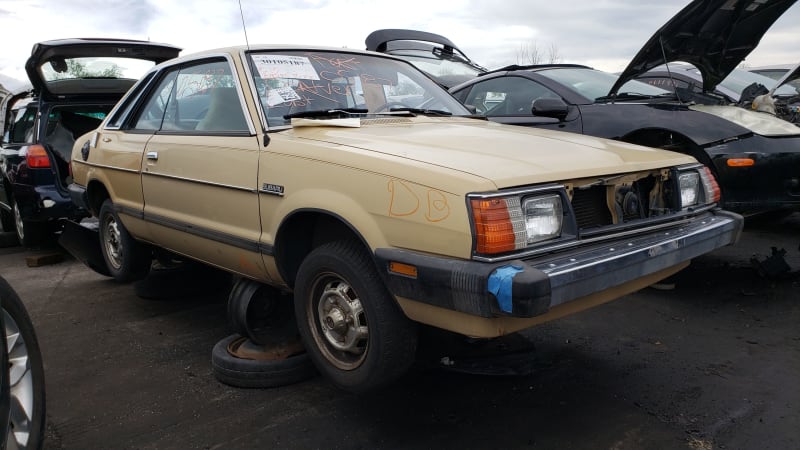
Continue reading Junkyard Gem: 1984 Subaru DL Hardtop Coupe
Junkyard Gem: 1984 Subaru DL Hardtop Coupe originally appeared on Autoblog on Mon, 31 May 2021 10:00:00 EDT. Please see our terms for use of feeds.
Permalink | Email this | CommentsGraveyard of Rusted Cars Kept Lake Michigan Erosion at Bay, and They're Still There
When conditions are right, you can still see the breakwall near the water's edge made out of old cars in Saint Joseph, Michigan.
from Latest Content - Car and Driver https://ift.tt/2SKUo1v
Win an EV: The best giveaways of the week, including a Tesla Model S
Filed under: Audi,Land Rover,Porsche,Tesla,Commerce,Electric

Continue reading Win an EV: The best giveaways of the week, including a Tesla Model S
Win an EV: The best giveaways of the week, including a Tesla Model S originally appeared on Autoblog on Mon, 31 May 2021 09:00:00 EDT. Please see our terms for use of feeds.
Permalink | Email this | Comments1992 Dodge Viper RT/10 vs. 1965 Shelby 427SC Cobra
In which the lesson seems to be that going 60 mph in a Town Car is not at all like going 60 on a skateboard.
from Latest Content - Car and Driver https://ift.tt/2SGkKlA
Tested: 2006 Chevy Corvette Z06 vs. 2006 Dodge Viper SRT10
From the Archive: Two tire punishers face off in a Motor City grudge match. It's not going to be pretty.
from Latest Content - Car and Driver https://ift.tt/3g09Tur
Is a v4 better than a V6?
Is a v4 better than a V6?
With recent improvements in engine technology, 4-cylinder engines have become increasingly powerful while V6 engines are more fuel efficient than ever, significantly narrowing the gap between four- and six-cylinder vehicles. A well-functioning 1991 V6 engine is likely to be outperformed by a four-cylinder model today.How do 4-Cylinder and V6 Engines Differ? | Sun Devil Auto
2010 Cadillac Truck SRX FWD V6-3.0L Page 359
2010 Cadillac Truck SRX FWD V6-3.0L Page 359
The liftgate motor is a bi-directional motor and open or close operation is the result of the direction of the motor rotation. The liftgate control
module controls the liftgate motor through the control circuits by supplying power and ground in the appropriate polarity. The motor control
circuits are monitored by the liftgate control module prior to activation for a high or low condition and during motor operation for any irregular
current flow conditions.
Conditions for Running the DTC
* The system voltage is 9-16 V.
* Power open or close function is initiated.
Conditions for Setting the DTC
B396A 01
The liftgate control module detects a short to voltage in a liftgate motor control circuit.
B396A 02
The liftgate control module detects a short to ground in a liftgate motor control circuit.
B396A 04
The liftgate control module detects an open/high resistance in a liftgate motor control circuit or the liftgate control module B+ circuit. A short to
ground in the liftgate control module B+ circuit.
Action Taken When the DTC Sets
The power liftgate may be inoperative in the power mode and in the manual mode.
Conditions for Clearing the DTC
* The DTC will be current for as long as the fault is present.
* When the fault is no longer present, the DTC will be a history DTC.
* A history DTC will clear after 50 ignition cycles.
Diagnostic Aids
* If the liftgate will not release from the closed position, refer to Opening the Liftgate Without Electrical Power (See: Body and Frame/Doors,
Hood and Trunk/Trunk / Liftgate/Service and Repair/Procedures) for the appropriate procedure
* Whenever the liftgate control module loses power or is disconnected, the ignition must be cycled OFF then ON in order to reactivate the
liftgate control module.
* DTC B396A 01 may set as current or history when the liftgate control module detects erratic voltage levels in the electrical system and does
not affect the operation of the power liftgate. If this DTC is set and the liftgate functions normally, clear the DTC
Reference Information
Schematic Reference
Liftgate Schematics (See: Body and Frame/Locks/Diagrams/Electrical Diagrams/Liftgate Schematics)
Connector End View Reference
Component Connector End Views (See: Diagrams/Connector Views/Connector End Views By Name)
Description and Operation
Liftgate Description and Operation (See: Body and Frame/Doors, Hood and Trunk/Trunk / Liftgate/Description and Operation/Liftgate)
Electrical Information Reference
* Testing for Intermittent Conditions and Poor Connections (See: Testing and Inspection/Component Tests and General Diagnostics/General
Electrical Diagnostic Procedures/Circuit Testing/Testing for Intermittent Conditions and Poor Connections)
* Circuit Testing (See: Testing and Inspection/Component Tests and General Diagnostics/General Electrical Diagnostic Procedures/Circuit
Testing/Circuit Testing)
* Wiring Repairs (See: Testing and Inspection/Component Tests and General Diagnostics/General Electrical Diagnostic Procedures/Wiring
Repairs/Wiring Repairs)
* Connector Repairs (See: Testing and Inspection/Component Tests and General Diagnostics/General Electrical Diagnostic
Procedures/Connector Repairs/Connector Repairs)
Scan Tool Reference
Control Module References (See: Testing and Inspection/Programming and Relearning) for scan tool information
Summer used buys | 2006-2015 Mazda Miata
Filed under: Mazda,Used Car Buying,Convertible
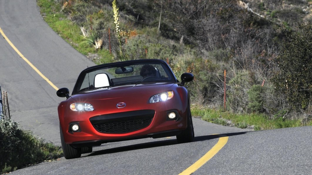
Continue reading Summer used buys | 2006-2015 Mazda Miata
Summer used buys | 2006-2015 Mazda Miata originally appeared on Autoblog on Mon, 31 May 2021 08:00:00 EDT. Please see our terms for use of feeds.
Permalink | Email this | CommentsWhat is the cheapest best car?
We've rounded up the eight least expensive new cars you can buy today to help budget-minded shoppers find a brand-new vehicle.Nissan Versa Sedan 鈥?$12,815. ... Chevrolet Spark 鈥?$12,995. ... Mitsubishi Mirage 鈥?$13,790. ... smart fortwo 鈥?$14,090. ... Ford Fiesta 鈥?$14,790. ... Kia Rio 鈥?$14,815. ... Nissan Versa Note 鈥?$15,005.More items...The 8 Least Expensive New Cars You Can Buy Today - Autotrader
2010 Mercedes Benz C 300 (204.054) V6-3.0L (272.947) Page 1940
1.1.3.2.1.4. Check power supply at control unit N15/3 (ETC [EGS] control unit).
Test 1.1.3.2.1.4.1: Guided test
1.1.3.2.1.4.1. Guided test
Operation number of operation texts and work units or standard texts and flat rates:27-0641Possible cause
- Battery has incorrect charge state or is faulty.
- Local undervoltage of component N15/3 (ETC [EGS] control unit)
Test sequence
- Erase fault memory.
Continue with button "F2"
Warning!Communication with ECU required.
1.1.3.2.1.5. Check power supply at control unit N15/5 (Electronic selector lever module control unit).
Operation number of operation texts and work units or standard texts and flat rates:27-0641Test sequence
- Switch off ignition.
- Disconnect connector at component N15/5 (Electronic selector lever module control unit).
- Switch on ignition.
- [A.2] Measure direct voltage with multimeter between 2 and 1 [A.1]
Status of relevant actual value:
- Supply voltage (tml. 15):Warning! Communication with ECU required.
Specified value
- Voltage[7.0...16.0] V
Question
- Is the measurement value OK?
YES
The measurement value is OK.Possible cause and remedy
- Replace component Floor-mounted shift.
End of test
NO
The measurement value is not OK.Possible cause and remedy
- Check fuse f55 (voltage supply from control unit ESM) in component N10/1 (Front SAM control unit with fuse and relay module).
- Check all affected plugs, connectors and electrical components for damage, loose contact, corrosion etc. and repair if necessary.
End of test
1.1.3.2.1.6. Check power supply at control unit N15/6 (Sprintshift control module).
Test voltage supply of circuit 30.
Operation number of operation texts and work units or standard texts and flat rates:26-0641Test sequence
- Switch off ignition.
- Connect socket box to component N15/6 (Sprintshift control module).
- Measure direct voltage with multimeter between sockets (B.36) 36 and (B.38) 38 of the 126-pole socket box tester.
Is Porsche Macan worth the money?
Overall, the 2019 Porsche Macan offers more customization options than most of its competitors. Although this can rack up extra costs, some of these options are truly worth it. Regardless of which trim level you opt for, you will be getting a vehicle that puts in a strong driving performance.Why Buy a 2019 Porsche Macan? w/ Pros vs Cons & Buying Advice
2010 Cadillac Truck SRX FWD V6-3.0L Page 497
2010 Cadillac Truck SRX FWD V6-3.0L Page 497
* Perform the Diagnostic System Check - Vehicle (See: Testing and Inspection/Initial Inspection and Diagnostic Overview/Diagnostic System
Check - Vehicle) prior to using this diagnostic procedure.
* Review Strategy Based Diagnosis (See: Testing and Inspection/Initial Inspection and Diagnostic Overview/Strategy Based Diagnosis) for an
overview of the diagnostic approach.
* Diagnostic Procedure Instructions (See: Testing and Inspection/Initial Inspection and Diagnostic Overview/Diagnostic Procedure
Instructions) provides an overview of each diagnostic category.
DTC Descriptors
DTC B1735 02
- Driver Seat Front Up Switch Circuit Short to Ground
DTC B1740 02
- Driver Seat Front Down Switch Circuit Short to Ground
DTC B1745 02
- Driver Seat Rear Up Switch Circuit Short to Ground
DTC B1750 02
- Driver Seat Rear Down Switch Circuit Short to Ground
DTC B1755 02
- Driver Seat Assembly Forward Switch Circuit Short to Ground
DTC B1760 02
- Driver Seat Assembly Rearward Switch Circuit Short to Ground
DTC B1815 02
- Driver Seat Recline Forward Switch Circuit Short to Ground
DTC B1820 02
- Driver Seat Recline Rearward Switch Circuit Short to Ground
Diagnostic Fault Information
Circuit/System Description
The seat memory control module supplies a reference voltage to each signal circuit of the driver seat adjuster switch. When the power seat switches
are pressed, the appropriate signal circuit from the seat memory control module is pulled low through the switch contacts indicating the power seat
command. The seat memory control module then commands the driver seat to move in response to the switch signals.
Conditions for Running the DTC
* DTC B1325 must not be present.
* Module battery voltage must be between 9 - 16 V.
Conditions for Setting the DTC
2010 Cadillac Truck SRX AWD V6-3.0L Page 1774
2010 Cadillac Truck SRX AWD V6-3.0L Page 1774
* Perform the Diagnostic System Check - Vehicle (See: Testing and Inspection/Initial Inspection and Diagnostic Overview/Diagnostic System
Check - Vehicle) prior to using this diagnostic procedure.
* Review Strategy Based Diagnosis (See: Testing and Inspection/Initial Inspection and Diagnostic Overview/Strategy Based Diagnosis) for an
overview of the diagnostic approach.
* Diagnostic Procedure Instructions (See: Testing and Inspection/Initial Inspection and Diagnostic Overview/Diagnostic Procedure
Instructions) provides an overview of each diagnostic category.
DTC Descriptors
DTC P0850
- Park/Neutral Position (PNP) Switch Circuit
DTC P0851
- Park/Neutral Position (PNP) Switch Circuit Low Voltage
DTC P0852
- Park/Neutral Position (PNP) Switch Circuit High Voltage
Diagnostic Fault Information
Typical Scan Tool Data
Circuit/System Description
The transmission manual shift shaft switch assembly, also known as the Internal Mode Switch (IMS), is a sliding contact switch attached to the
manual shift shaft inside the transmission case. The Park/Neutral Position (PNP) Switch is integrated into the IMS and connects to the Transmission
Control Module (TCM) lead-frame through a short wire harness. The circuit uses the TCM as a pass-through connector only. The Park/Neutral
Signal is sent from the park/neutral switch directly to the engine control module (ECM) and is used for engine start enable.
Conditions for Running the DTC
* Ignition voltage is between 8-18 volts.
* Engine speed is greater than 1000 RPM.
Conditions for Setting the DTC
P0850 and P0851
* The ECM detects the Park/Neutral switch signal equals 0 volts (Park/Neutral) when the IMS reports a Drive range for 0.2 second.
* TP is equal to or greater than 10 percent.
* Engine torque is equal to or greater than 75 Nm (55 lb ft).
* Vehicle speed is equal or greater than 10 km/h (6 mph).
P0852
The ECM detects the Park/Neutral switch signal equals 12 volts (In-Gear) when the IMS reports a Park/Neutral range for 0.2 second.
Action Taken When the DTC Sets
* DTCs P0850, P0851, and P0852 are Type C DTCs.
* The ECM uses IMS Range for engine start-up.
Conditions for Clearing the DTC
DTCs P0850, P0851, and P0852 are Type C DTCs.
Mercedes-Benz: 30 Years of the 500 E Review Specification & Presentation
via https://youtu.be/jyWaLkVxwoY
the all-new 2022 Ford F-150 Raptor* the most off-road capable and connected F-150 Raptor ever
via https://youtu.be/ffWbA3vEBh8
Which luxury SUV holds its value best?
Which luxury SUV holds its value best?
10 Luxury SUVs With the Best Resale Value2018 Cadillac Escalade. ... 2018 Porsche Macan. ... 2019 Porsche Cayenne. ... 2018 Land Rover Discovery. ... 2018 Land Rover Discovery Sport. ... 2019 Mercedes-Benz G-Class. ... 2018 Toyota Land Cruiser. ... 2018 Lincoln Navigator.More items...10 Luxury SUVs With the Best Resale Value | Autobytel.com
Mercedes-Benz: 30 Years of the 500 E Review Specification & Presentation
Mercedes-Benz: 30 Years of the 500 E Review Specification & Presentation.
the all-new 2022 Ford F-150 Raptor* the most off-road capable and connected F-150 Raptor ever
the all-new 2022 Ford F-150 Raptor* the most off-road capable and connected F-150 Raptor ever An all-new five-link rear suspension, electronically controlled ...
2022 Acura MDX VS Lexus RX 350L 2021 Specification & Presentation
2021 Lexus RX 350L vs 2022 Acura MDX Review & Comparison Acura MDX 2022.
Acura MDX Road Test VS Infiniti QX60 Review
2019 Infiniti QX60 Road Test & Review vs. the 2019 Acura MDX Road Test.
Sunday, May 30, 2021
2010 Mercedes Benz C 300 (204.054) V6-3.0L (272.947) Page 998
Test 3.2: Test current consumption of component Y110 (Three-disk thermostat valve).
3.1. Component Y110 (Three-disk thermostat valve) is mechanically damaged or it sticks.
Test 3.1.1: Y110 (Three-disk thermostat valve) : Coolant temperature is not reached.
Test 3.1.2: Y110 (Three-disk thermostat valve) : Coolant temperature is too high.
3.1.1. Y110 (Three-disk thermostat valve) : Coolant temperature is not reached.
Warning!Communication with ECU required.
3.1.2. Y110 (Three-disk thermostat valve) : Coolant temperature is too high.
Warning!Communication with ECU required.
3.2. Test current consumption of component Y110 (Three-disk thermostat valve).
Figure legend
- A -ConnectionTest cable 35-pin socket box
- 001 -Sockets of component N3/10 (ME-SFI [ME] control unit)
- 05 -35-pin socket box
- 050 -126-pin socket box
- 108 -Test cable 266 589 01 63 00
- N3/10 (ME-SFI [ME] control unit)
- II 1-63ConnectionTest cable
- III 64-126ConnectionTest cable
Warning!
- Connection A of test cable 108 may NOT be connected to connection B of the 126-pin socket box (050).
Continue to test with button F2
Test sequence
- Measure direct current with multimeter between sockets [F.4] 100 and [M.54] 54 of the 126-pole socket box tester.
- Switch on ignition.
Specified value
- Amperage[0.6...1.2] A
Do Jeep Cherokees have a lot of problems?
The 2014 and 2015 Jeep Cherokees currently have 659 and 643 owner-reported complaints; an astoundingly-high amount. It's easy to see a trend between the Cherokee's transmission and engine performance. ... More than 80 owners complain of engine issues, sharing the same 鈥渟talling鈥?problems as 2019 model year owners.Apr. 2, 2020The 2019 Jeep Cherokee Is Receiving Some Alarming Complaints ...
2010 Cadillac Truck SRX AWD V6-3.0L Page 1571
2010 Cadillac Truck SRX AWD V6-3.0L Page 1571
* Battery voltage is greater than 11.5 V.
Conditions for Setting the DTC
P0572
This DTC will set when the ECM detects a short to ground or an open on the discrete brake signal circuit when the serial data message from the
BCM indicates the brakes are applied. This diagnostic will run when the serial data message and the voltage signal on the brake switch signal
circuit do not match for 8 out 10 times, and the condition is present for greater than 2 seconds.
P0573
This DTC will set when the ECM detects a short to voltage on the discrete brake signal circuit when the serial data message from the BCM
indicates the brakes are NOT applied. This diagnostic will run when the serial data message and the voltage signal on the brake switch signal circuit
do not match for 8 out 10 times, and the condition is present for greater than 2 seconds.
Actions Taken When the DTC Sets
* The malfunction indicator lamp (MIL) will not illuminate.
* The cruise control system is disabled.
Conditions for Clearing the DTC
* The condition responsible for setting the DTC no longer exists.
* A history DTC will clear after 40 malfunction-free ignition cycles have occurred.
Reference Information
Schematic Reference
Cruise Control Schematics (See: Cruise Control/Diagrams/Electrical Diagrams)
Connector End View Reference
Component Connector End Views (See: Diagrams/Connector Views/Connector End Views By Name)
Description and Operation
Cruise Control Description and Operation (See: Cruise Control/Description and Operation)
Electrical Information Reference
* Circuit Testing (See: Testing and Inspection/Component Tests and General Diagnostics/General Electrical Diagnostic Procedures/Circuit
Testing/Circuit Testing)
* Connector Repairs (See: Testing and Inspection/Component Tests and General Diagnostics/General Electrical Diagnostic
Procedures/Connector Repairs/Connector Repairs)
* Testing for Intermittent Conditions and Poor Connections (See: Testing and Inspection/Component Tests and General Diagnostics/General
Electrical Diagnostic Procedures/Circuit Testing/Testing for Intermittent Conditions and Poor Connections)
* Wiring Repairs (See: Testing and Inspection/Component Tests and General Diagnostics/General Electrical Diagnostic Procedures/Wiring
Repairs/Wiring Repairs)
Scan Tool Reference
Control Module References (See: Testing and Inspection/Programming and Relearning)for scan tool information
Circuit/System Testing
1. Ignition OFF, disconnect the X1 (LF1) or X2 (LAU) harness connector at the K20 ECM.
2. Connect a test lamp between the appropriate signal circuit terminal listed below and ground.
* Terminal 57 (LF1)
* Terminal 52 (LAU)
3. Ignition ON, verify the test lamp turns ON and OFF when pressing and releasing the brake pedal.
瀚慖f the test lamp is always ON, test the signal circuit for a short to voltage. If the circuit tests normal, replace the K9 BCM.
瀚慖f the test lamp is always OFF, test the signal circuit for a short to ground or an open/high resistance. If the circuit tests normal, replace
the K9 BCM.
4. If all circuits test normal, replace the K20 ECM.
Repair Instructions
Perform the Diagnostic Repair Verification (See: Verification Tests) after completing the diagnostic procedure.
2018 Subaru Crosstrek
Review, Pricing, and Specs
from Latest Content - Car and Driver https://ift.tt/3uCfoVs
2010 Cadillac Truck SRX AWD V6-3.0L Page 1595
2010 Cadillac Truck SRX AWD V6-3.0L Page 1595
* DTCs P0111, P0112, P0113 are not set.
* DTC P2610 runs on ECM power down.
Conditions for Setting the DTC
The ECM detects an internal failure or incomplete or incorrect programming.
Action Taken When the DTC Sets
* DTCs P0601, P0602, P0603, P0604, P0606, P062B, P062F, P0630 and P16F3 are Type A DTCs.
* DTC P2610 is a Type B DTC.
Conditions for Clearing the DTC
* DTCs P0601, P0602, P0603, P0604, P0606, P062B, P062F, P0630 and P16F3 are Type A DTCs.
* DTC P2610 is a Type B DTC.
Diagnostic Aids
Low voltage or a momentary loss of power or ground to the ECM may cause a DTC to set. Verify for the following:
* The battery cables are clean and tight, and the battery is fully charged-Refer to Battery Inspection/Test (See: Starting and Charging/Testing
and Inspection/Component Tests and General Diagnostics/Battery Inspection/Test).
* The ECM ground circuits do not have an open or high resistance
* The ECM power circuits do not have an open, short to ground, or high resistance
Reference Information
Schematic Reference
Engine Controls Schematics (LAU) (See: Diagrams/Electrical Diagrams/Powertrain Management/System Diagram)Engine Controls Schematics
(LF1) (See: Diagrams/Electrical Diagrams/Powertrain Management/System Diagram)
Connector End View Reference
Component Connector End Views (See: Diagrams/Connector Views/Connector End Views By Name)
Electrical Information Reference
* Circuit Testing (See: Testing and Inspection/Component Tests and General Diagnostics/General Electrical Diagnostic Procedures/Circuit
Testing/Circuit Testing)
* Connector Repairs (See: Testing and Inspection/Component Tests and General Diagnostics/General Electrical Diagnostic
Procedures/Connector Repairs/Connector Repairs)
* Testing for Intermittent Conditions and Poor Connections (See: Testing and Inspection/Component Tests and General Diagnostics/General
Electrical Diagnostic Procedures/Circuit Testing/Testing for Intermittent Conditions and Poor Connections)
* Wiring Repairs (See: Testing and Inspection/Component Tests and General Diagnostics/General Electrical Diagnostic Procedures/Wiring
Repairs/Wiring Repairs)
DTC Type Reference
Powertrain Diagnostic Trouble Code (DTC) Type Definitions (See: Diagnostic Trouble Code Descriptions/Powertrain Diagnostic Trouble Code
(DTC) Type Definitions)
Scan Tool Reference
Control Module References (See: Testing and Inspection/Programming and Relearning) for scan tool information
Circuit/System Verification
1. Observe the DTC information with a scan tool. DTC P0601, P0602, P0603, P0604, P0606, P062B, P062F, P0630, P16F3, or P2610 should
not set.
2. Operate the vehicle within the Conditions for Running the DTC to verify the DTC does not reset. You may also operate the vehicle within the
conditions that you observed from the Freeze Frame/Failure Records data.
Circuit/System Testing
1. Ignition ON, clear the DTC information with a scan tool.
2. Observe the scan tool DTC information. Verify that DTC P0602 or P0630 does not set.
瀚慖f DTC P0602 or P0630 failed this ignition, reprogram the K20 ECM. Refer to Control Module References (See: Testing and
Inspection/Programming and Relearning). If the DTC resets, replace the K20 ECM.
3. Observe the DTC information with a scan tool. Verify that DTC P0601, P0603, P0604, P0606, P062B, P062F, P16F3, or P2610 does not set.
Helio Castroneves wins the Indy 500 for a 4th time
Filed under: Motorsports

Continue reading Helio Castroneves wins the Indy 500 for a 4th time
Helio Castroneves wins the Indy 500 for a 4th time originally appeared on Autoblog on Sun, 30 May 2021 17:12:00 EDT. Please see our terms for use of feeds.
Permalink | Email this | CommentsGT-R Times Two: Nissan Builds GT-R Camera Car to Film GT-R NISMO
Text
"Why settle for Mothra when you can have Godzilla? Mothra, the fictional Godzilla monster's nemesis, in this case is the typical high-performance SUV that filmmakers often use as camera cars. In the movies, Mothra lost out to Godzilla—and it's happened all over again: Nissan skipped the usual Porsche Cayenne-based camera rig for a GT-R, its sports car that goes by the nickname ""Godzilla,"" in order to film . . . another GT-R. "
Nissan put professional stunt driver Mauro Calo behind the wheel of the camera-rig GT-R and had him play a nice game of cat-and-mouse with the beastly 2020 GT-R NISMO. Are the two cars perfect equals? No. Blame the extra weight of the camera equipment the camera GT-R has to haul around, as well as the additional bodies assigned to operate the camera gimbal, the focus puller, and choreograph the on-track dance from within the car's cabin. The GT-R's small rear seats actually are used when conducting high-speed filming.
Still, the camera-rig GT-R is no slouch thanks to the plentiful power of its twin-turbo 3.8-liter V-6 engine, quick-reacting all-wheel-drive system, relatively low center of gravity, and sticky tires. It's the perfect camera car, it turns out, for chasing down another GT-R, NISMO or otherwise. Plus,
it gave Nissan an excuse to publicize its aging, but still potent, sports coupe—after all, Nissan didn't really need to build the thing in order to film the GT-R NISMO. But we sure are glad it did.
READ MORE
The Clinton- and Bush-Era Cars Still Sold Today
Text
"We hear it all the time: Keep politics out of MotorTrend. Well, you're in luck, because despite the political nature of this article's title, there are no political undertones to the text. Did you support Bill Clinton while Newt Gingrich and Ken Starr tried to take him down? Whatever. Were you hooting and hollering as George W. Bush spoke on the deck of the USS Abraham Lincoln under a ""Mission Accomplished"" banner? It's irrelevant. "
Neither of these presidents' accomplishments, failures, or policies matter. We're simply using their presidencies as a measure of time. After all, it's one thing to say an automaker's been selling the same basic car for a dozen years; it's another to realize an automaker first introduced a specific car it still sells while William Jefferson Clinton or George Walker Bush helmed the Executive Branch of the United States government.
This van represented the first redesign of General Motors full-size cargo and passenger vans since the early 1970s. The
and GMC Savana received modern styling and safety features, as well as stiff new underpinnings. Almost 25 years later, the vans soldier on. Minor facelifts and powertrain improvements helped the vans maintain some semblance of modernity over the years. That said, GM's full-size vans look and feel comparatively ancient next to more contemporary competitors such as the Ford Transit, Mercedes-Benz Sprinter, and Ram ProMaster.
Unlike consumer interest in mid-size pickups, which ebbs and flows like the Colorado River, the Nissan Frontier persists—a living fossil, like a horseshoe crab or a coelacanth. The Japanese automaker took the wraps off the truck at the
" and announced its arrival for the 2005 model year. Using a variant of the frame that underpins the full-size Nissan Titan pickup, the Frontier impressed us on its debut with its """
""" and available 265 horsepower 4.0-liter V-6 engine. Nissan rested on its laurels, though, and changed little about the model in the ensuing years. The brand finally made a noteworthy change to "
model year with the introduction of a new 3.8-liter V-6 engine, which makes 310 horses and replaces the truck's prior 4.0-liter V-6 and previously standard 2.5-liter four-cylinder engine. Powertrain aside, little else separates the 2005 and 2020 Nissan Frontiers.
The Toyota Tundra finally went toe-to-toe with the domestic full-size pickup trucks for the 2007 model year. Bold and brash, the second-generation Tundra carried over its predecessor's 4.0-liter V-6 and 4.7-liter V-8 engines, but also offered buyers a new 381-hp 5.7-liter V-8 option. Despite the thrust of its big bent-eight, the Tundra failed to take down the 2007 Chevrolet Silverado in a
. Small improvements included the arrival of a more modern 4.6-liter V-8 engine to replace the aging 4.7-liter unit, as well as
. In spite of this, the Tundra that Toyota sells today remains largely the same as the truck it introduced during Bush's second term in office.
Following the success of its Challenger concept car at the
, Dodge greenlit the rear-drive coupe for production. The 2008 Dodge Challenger arrived in high-horsepower SRT8 form boasting a 425-hp 6.1-liter V-8 that pushed the 197.7-inch long muscle car to
. Dodge added less powerful six- and eight-cylinder engine options for 2009, and an even rowdier
for the 2011 model year. The real party arrived for 2015, though, with an exterior and interior refresh and a new Hellcat trim, which included a 707-hp supercharged 6.2-liter V-8. The rip-snorting powertrain allowed the
to hit the mile-a-minute mark in 3.7 seconds and cross the quarter-mile after 11.7 seconds at 125.4 mph. Dodge then took things a couple of steps further with the 840-hp
and the 797-hp
. Although Dodge continues to develop the Challenger, the big coupe remains—at its core—fundamentally the same vehicle it was more than a decade ago.
The 2008 Dodge Grand Caravan ditched its predecessor's jelly bean-like looks for square wares that loosely resemble the styling of the original 1984 Caravan. Unfortunately, the model's plastic-heavy interior failed to impress. Dodge quickly reworked the Grand Caravan with a
refresh that gave the minivan slightly less blocky styling details, a reworked interior, and a 3.6-liter V-6 underhood. After that, crickets. While the Grand Caravan's sibling, the Chrysler Town & Country, retired after the 2016 model year to make way for the arrival of the new Pacifica minivan, the Dodge keeps on chugging. Although the geriatric Grand Caravan remains a part of the 2020 Dodge lineup, it's due to disappear from the American brand's
.
Lexus and Toyota revealed new iterations of the LX and Land Cruiser for the 2008 model year, the former of which dons the name
, an homage to the 5.7-liter V-8 engine that rests underhood. Despite its name's lack of digits, the same engine motivates the Land Cruiser. Like prior iterations of these pricey SUVs, the latest LX 570 and Land Cruiser are big and boxy. Lexus made some minor improvements to the
", which received the brand's ""spindle"" grille design. The hulking luxury SUV benefitted from a more thorough reskin for 2016—coinciding with a facelift for the more utilitarian Land Cruiser. A dozen years on, though, these two Japanese SUVs still maintain much of the same mechanical pieces as the day Lexus and Toyota tore each models' wraps off. "
As goes the Tundra, so goes the Sequoia. One model year after Toyota revealed the redesigned Tundra, its SUV sibling received a full makeover. The body-on-frame people mover received a front end and dashboard like that of the Tundra, as well as new mechanical bits—such as an independent rear suspension and an optionally available 381-hp 5.7-liter V-8. While the Tundra received a thorough mid-cycle update for the 2014 model year, the Sequoia soldiers on largely unchanged from the day it broke cover at the
.
When it was introduced, the 2009 Dodge Journey brought crossover sensibilities to the American brand's largely car and SUV dominant model line. Although it offered handsome looks when new, the Journey's low-quality interior materials and middling powertrains (a standard 173-hp 2.4-liter I-4 and four-speed automatic transmission, and an optional 235-hp 3.5-liter V-6 and six-speed automatic) failed to impress. Dodge updated the model with a higher-quality interior, revised styling, and a new V-6 engine for 2011. While the 283-hp unit brought more liveliness to the Journey and allowed the 4,350-pound, all-wheel-drive crossover to hit 60 mph in
, the standard, pokey I-4 remained a sore spot. The addition of a butcher looking Crossroad package added somewhat to the Journey's appeal, however, the loss of the V-6 engine for the 2020 model year ultimately makes this aging crossover an even harder sell in today's competitive marketplace.
Dodge's last pickup entered the market for the 2009 model year with evolutionary styling and a revolutionary (by truck standard's) coil spring rear suspension setup. In the early 2010s, Ram formally broke away from Dodge and the former Dodge Ram 1500 pickup truck received the simpler Ram 1500 nomenclature. The Ram-badged truck became the
for 2019 in order to separate it from the
. Despite the two Rams filling the same essential role in the truck brand's model line, the 1500 Classic continues on as an entry-level alternative to the dynamically superior,
winning, new 1500.
Approximately six years after the arrival of the reborn Nissan 350Z sports car, the Japanese brand let loose the thoroughly reworked 370Z. As its name implies, the new car traded its predecessor's 306-hp 3.5-liter V-6 for a 332-hp 3.7-liter unit. With nearly four inches cut from its wheelbase, more than two inches added to its rear track, and a few pounds slashed from its curb weight, the new Z car promised noteworthy performance improvements. Unfortunately, the engine's extra displacement results in
. Although initially available in both coupe and roadster form, Nissan culled the drop-top from the lineup for the 2020 model year, leaving the hard-topped model as the sole Z option. Fortunately, the long-lived 370Z is due to go out to pasture in order to make room for a
.
After years of begging, North American consumers finally got the chance to own Nissan's legendary GT-R for the 2009 model year. The redesigned super-coupe no longer served as a variant of the Skyline (sold here—at the time—as the Infiniti G37), and instead becomes its own dedicated model. With all-wheel-drive, a slick six-speed dual-clutch automatic transmission, a 480-hp twin-turbocharged 3.8-liter V-6 engine, and a starting price just north of $70,000, the GT-R offered six-figure performance in a five-figure package. The car's dynamic capabilities and inherent value earned it our
award. Nissan continued to improve the model throughout the next decade, with the current, entry-level GT-R making a full 565-hp from its twin-turbo six-cylinder engine. The car also costs a good deal more these days, with the least expensive 2020 GT-R ringing in at $115,335—more than $40,000 higher than the 2009 GT-R's cost of entry.
2021.5 Nissan GT-R NISMO Special Edition First Look: Need Mo' NISMO?
Nissan's latest take on its GT-R sports car comes in the form of the NISMO Special Edition. The limited-run model, which is due to arrive in the United States this fall, straddles the line between the 2021 and 2022 model years, which is why the Japanese brand instead intends to market and sell this car on our shores as a 2021.5 model.
Model year semantics aside, buyers of this extra-special GT-R are due for a real treat. Well, visually at least. Although the GT-R NISMO Special Edition maintains the GT-R NISMO's 600-hp twin-turbocharged 3.8-liter V-6, six-speed dual-clutch automatic transmission, and all-wheel-drive system, it does offer trim-exclusive styling details including a coat of Stealth Gray paint, RAYS-sourced 20-inch forged aluminum-alloy wheels with red accents, an exposed—albeit under clearcoat—carbon-fiber hood, and the inclusion of Nissan's latest logo design throughout. The head-turning addition to the GT-R Nismo line also sports a Special Edition-specific plaque on the engine, which includes the name of the master technician that hand-assembled each of these six-figure sports cars' hearts.
Well, we assume the GT-R NISMO Special Edition will wear a six-figure price tag given the 2021 GT-R NISMO starts at $212,535 (and the plain-Jane 565-hp GT-R stickers for $115,335). Nevertheless, Nissan's still keeping mum on pricing information for the NISMO Special Edition, as well as how many it'll build. Smart money is
on writing a check for well over $200,000 to snag one of these puppies. Good looks come at a cost. Right?
2010 Cadillac Truck SRX FWD V6-3.0L Page 143
2010 Cadillac Truck SRX FWD V6-3.0L Page 143
Check - Vehicle) prior to using this diagnostic procedure.
* Review Strategy Based Diagnosis (See: Testing and Inspection/Initial Inspection and Diagnostic Overview/Strategy Based Diagnosis) for an
overview of the diagnostic approach.
* Diagnostic Procedure Instructions (See: Testing and Inspection/Initial Inspection and Diagnostic Overview/Diagnostic Procedure
Instructions) provides an overview of each diagnostic category.
DTC Descriptors
DTC B0014 01
- Driver Seat Side Air Bag Deployment Loop Short to Battery
DTC B0014 02
- Driver Seat Side Air Bag Deployment Loop Short to Ground
DTC B0014 04
- Driver Seat Side Air Bag Deployment Loop Open
DTC B0014 0D
- Driver Seat Side Air Bag Deployment Loop High Resistance
DTC B0014 0E
- Driver Seat Side Air Bag Deployment Loop Low Resistance
DTC B0015 01
- Driver Seat Belt Retractor Pretensioner Deployment Loop Short to Battery
DTC B0015 02
- Driver Seat Belt Retractor Pretensioner Deployment Loop Short to Ground
DTC B0015 04
- Driver Seat Belt Retractor Pretensioner Deployment Loop Open
DTC B0015 0D
- Driver Seat Belt Retractor Pretensioner Deployment Loop High Resistance
DTC B0015 0E
- Driver Seat Belt Retractor Pretensioner Deployment Loop Low Resistance
DTC B0016 01
- Left Roof Rail Air Bag Deployment Loop Short to Battery
DTC B0016 02
- Left Roof Rail Air Bag Deployment Loop Short to Ground
DTC B0016 04
- Left Roof Rail Air Bag Deployment Loop Open
DTC B0016 0D
- Left Roof Rail Air Bag Deployment Loop High Resistance
DTC B0016 0E
- Left Roof Rail Air Bag Deployment Loop Low Resistance
DTC B0019 01
- Passenger Instrument Panel Air Bag Deployment Loop Stage 1 Short to Battery
DTC B0019 02
- Passenger Instrument Panel Air Bag Deployment Loop Stage 1 Short to Ground
DTC B0019 04
- Passenger Instrument Panel Air Bag Deployment Loop Stage 1 Open
DTC B0019 0D
- Passenger Instrument Panel Air Bag Deployment Loop Stage 1 High Resistance
DTC B0019 0E
- Passenger Instrument Panel Air Bag Deployment Loop Stage 1 Low Resistance
DTC B0020 01
- Passenger Instrument Panel Air Bag Deployment Loop Stage 2 Short to Battery
2010 Mercedes Benz C 300 (204.054) V6-3.0L (272.947) Page 2357
- If fault occurs again:Check alternator.Communication with ECU required
- The quiescent current is too high.Test quiescent current.
NO
Figure legend 1:N71 (Headlamp range adjustment control module)Figure legend 2:N10/1 (Driver-side SAM control unit with fuse and relay
module)Test prerequisite
- The relevant actual value is not okay.
- Battery voltage is OK.
- Fuse N10/1f52 (Fuse 52) is OK.
Test sequence
- Switch off ignition.
- Disconnect connector at component N71 (Headlamp range adjustment control module).
- Measure direct voltage with multimeter between sockets (N71) 20 and (N71) 19
- Switch on ignition.
Specified value:Voltage = [11.0...14.5] VQuestion
- Is the measurement value OK?
SSC Gave the Track-Only Tuatara 500 More Horsepower
If the normal Tuatara just isn't crazy enough for you, the American supercar maker now has two even more extreme trims available.
from Latest Content - Car and Driver https://ift.tt/3p8ClP1
2018 Land Rover Range Rover Velar
Review, Pricing, and Specs
from Latest Content - Car and Driver https://ift.tt/34vLd7Z
Lamborghini Urus pair completes 4,000-mile trip across Japan
Filed under: Lamborghini,Crossover,Luxury
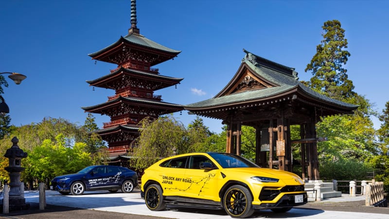
Continue reading Lamborghini Urus pair completes 4,000-mile trip across Japan
Lamborghini Urus pair completes 4,000-mile trip across Japan originally appeared on Autoblog on Sun, 30 May 2021 12:00:00 EDT. Please see our terms for use of feeds.
Permalink | Email this | CommentsSam Correro Built the TransAmerica Trail on Accident, and with a Lot of Work
In 1984, the motorcycle enthusiast began searching for a path less travelled, and then he just kept going and going and going.
from Latest Content - Car and Driver https://ift.tt/3fxfwRS
San Francisco residents debate whether to reopen car-free streets
Filed under: Transportation Alternatives

Continue reading San Francisco residents debate whether to reopen car-free streets
San Francisco residents debate whether to reopen car-free streets originally appeared on Autoblog on Sun, 30 May 2021 11:00:00 EDT. Please see our terms for use of feeds.
Permalink | Email this | CommentsRemoving highways could improve cities without increasing traffic
Filed under: Read This,Infrastructure

Continue reading Removing highways could improve cities without increasing traffic
Removing highways could improve cities without increasing traffic originally appeared on Autoblog on Sun, 30 May 2021 10:00:00 EDT. Please see our terms for use of feeds.
Permalink | Email this | Comments2010 Cadillac Truck SRX AWD V6-3.0L Page 1663
2010 Cadillac Truck SRX AWD V6-3.0L Page 1663
Voltage on position switch 1 and position switch 2 is less than 0.127 V for 100 ms continuously after 2 consecutive times.
P0708
Voltage on position switch 1 and position switch 2 is more than 4.87 V for 100 ms continuously after 2 consecutive times.
Action Taken When the DTC Sets
* DTCs P0706, P0707, and P0708 are Type A DTCs.
* The TCM freezes transmission adaptive functions.
* If output speed sensor is 0 RPM, Range is D, 2nd gear is hold and service mode will be set.
* The engine start is locked after engine has stopped.
Conditions for Clearing the DTC
* DTCs P0706, P0707, and P0708 are Type A DTCs.
* Voltage of two selector position sensor are within 0.127-4.87 V and sum of two position sensor voltage has deviation within 0.29 V from
standard value 5 V.
Reference Information
Schematic Reference
Automatic Transmission Controls Schematics (See: Transmission and Drivetrain/Automatic Transmission/Transaxle/Diagrams/Electrical
Diagrams)
Connector End View Reference
Component Connector End Views (See: Diagrams/Connector Views/Connector End Views By Name)
Description and Operation
Transmission Component and System Description (See: Transmission and Drivetrain/Automatic Transmission/Transaxle/Description and
Operation/AF40-6 - Automatic Transmission/Transmission Component and System Description)
Electrical Information Reference
* Circuit Testing (See: Testing and Inspection/Component Tests and General Diagnostics/General Electrical Diagnostic Procedures/Circuit
Testing/Circuit Testing)
* Connector Repairs (See: Testing and Inspection/Component Tests and General Diagnostics/General Electrical Diagnostic
Procedures/Connector Repairs/Connector Repairs)
* Testing for Intermittent Conditions and Poor Connections (See: Testing and Inspection/Component Tests and General Diagnostics/General
Electrical Diagnostic Procedures/Circuit Testing/Testing for Intermittent Conditions and Poor Connections)
* Wiring Repairs (See: Testing and Inspection/Component Tests and General Diagnostics/General Electrical Diagnostic Procedures/Wiring
Repairs/Wiring Repairs)
DTC Type Reference
Powertrain Diagnostic Trouble Code (DTC) Type Definitions (See: Diagnostic Trouble Code Descriptions/Powertrain Diagnostic Trouble Code
(DTC) Type Definitions)
Scan Tool Reference
Control Module References (See: Testing and Inspection/Programming and Relearning) for scan tool information
Circuit/System Verification
1. If there are any other transmission DTCs set, diagnose those DTCs first. Refer to Diagnostic Trouble Code (DTC) List - Vehicle (See:
Diagnostic Trouble Code Descriptions/Diagnostic Trouble Code (DTC) List - Vehicle).
Note: It is especially important to closely observe the Park and Neutral to Drive transitional positions while moving the shift lever and
observing for possible misalignment or slack in the shifter mechanism.
2. Ignition ON, observe the scan tool Transmission Range Switch parameter while slowly moving the gear shift lever from Park and through all
ranges. Verify the gear shift lever position matches the scan tool parameter.
瀚慖f not within the specified value, refer to Range Selector Lever Cable Adjustment (See: Transmission and Drivetrain/Automatic
Transmission/Transaxle/Shift Linkage/Shift Cable/Adjustments) and Transmission Adaptive Functions (See: Transmission and
Drivetrain/Automatic Transmission/Transaxle/Description and Operation/AF40-6 - Automatic Transmission/Transmission Adaptive
Functions).
3. Ignition ON, observe the scan tool Transmission Range Switch parameter while slowly moving the gear shift lever from Park and through all
ranges. Verify the gear shift lever position matches the scan tool parameter.
Morgan Makes Minor Updates to Its 2022 Lineup
The instantly recognizable Plus Four and Plus Six cars feature the same distinct styling, same sporty character, and a little more comfort.
from Latest Content - Car and Driver https://ift.tt/3vzrgco
Take a retro road trip in this 1988 Dodge Caravan
Filed under: Dodge,Auctions,Minivan/Van,Classics
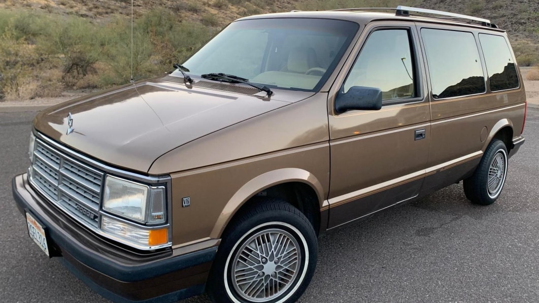
Continue reading Take a retro road trip in this 1988 Dodge Caravan
Take a retro road trip in this 1988 Dodge Caravan originally appeared on Autoblog on Sun, 30 May 2021 09:00:00 EDT. Please see our terms for use of feeds.
Permalink | Email this | Comments2021 Ford F-150 First Drive Review | Calm before the Lightning storm
Filed under: Green,Ford,Green Automakers,First Drives,Truck,Hybrid
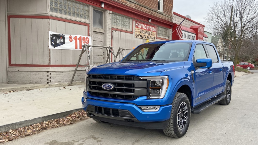
Continue reading 2021 Ford F-150 First Drive Review | Calm before the Lightning storm
2021 Ford F-150 First Drive Review | Calm before the Lightning storm originally appeared on Autoblog on Sun, 30 May 2021 08:00:00 EDT. Please see our terms for use of feeds.
Permalink | Email this | CommentsTesla update activates the in-car camera for driver monitoring
Filed under: Green,Tesla,Safety,Technology,Electric
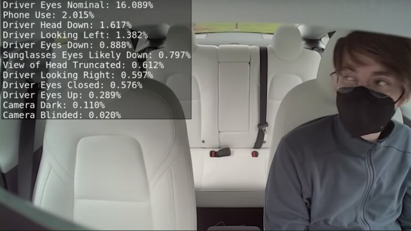
Continue reading Tesla update activates the in-car camera for driver monitoring
Tesla update activates the in-car camera for driver monitoring originally appeared on Autoblog on Sun, 30 May 2021 07:00:00 EDT. Please see our terms for use of feeds.
Permalink | Email this | CommentsHow long do brake pads last?
about 40,000 milesBrake pads may last about 40,000 miles on average, but the range is quite expansive: Typically, it can be anywhere between 20,000 and 65,000 miles. Many factors affect the lifespan of your brake pads, from your driving habits to the type of brake pads you use.How Long Do Brake Pads Last? | Faulkner Honda
2010 Cadillac Truck SRX AWD V6-3.0L Page 1661
2010 Cadillac Truck SRX AWD V6-3.0L Page 1661
P0708
Voltage on position switch 1 and position switch 2 is more than 4.87 V for 100 ms continuously after 2 consecutive times.
Action Taken When the DTC Sets
* DTCs P0706, P0707, and P0708 are Type A DTCs.
* The TCM freezes transmission adaptive functions.
* If output speed sensor is 0 RPM, Range is D, 2nd gear is hold and service mode will be set.
* The engine start is locked after engine has stopped.
Conditions for Clearing the DTC
* DTCs P0706, P0707, and P0708 are Type A DTCs.
* Voltage of two selector position sensor are within 0.127-4.87 V and sum of two position sensor voltage has deviation within 0.29 V from
standard value 5 V.
Reference Information
Schematic Reference
Automatic Transmission Controls Schematics (See: Transmission and Drivetrain/Automatic Transmission/Transaxle/Diagrams/Electrical
Diagrams)
Connector End View Reference
Component Connector End Views (See: Diagrams/Connector Views/Connector End Views By Name)
Description and Operation
Transmission Component and System Description (See: Transmission and Drivetrain/Automatic Transmission/Transaxle/Description and
Operation/AF40-6 - Automatic Transmission/Transmission Component and System Description)
Electrical Information Reference
* Circuit Testing (See: Testing and Inspection/Component Tests and General Diagnostics/General Electrical Diagnostic Procedures/Circuit
Testing/Circuit Testing)
* Connector Repairs (See: Testing and Inspection/Component Tests and General Diagnostics/General Electrical Diagnostic
Procedures/Connector Repairs/Connector Repairs)
* Testing for Intermittent Conditions and Poor Connections (See: Testing and Inspection/Component Tests and General Diagnostics/General
Electrical Diagnostic Procedures/Circuit Testing/Testing for Intermittent Conditions and Poor Connections)
* Wiring Repairs (See: Testing and Inspection/Component Tests and General Diagnostics/General Electrical Diagnostic Procedures/Wiring
Repairs/Wiring Repairs)
DTC Type Reference
Powertrain Diagnostic Trouble Code (DTC) Type Definitions (See: Diagnostic Trouble Code Descriptions/Powertrain Diagnostic Trouble Code
(DTC) Type Definitions)
Scan Tool Reference
Control Module References (See: Testing and Inspection/Programming and Relearning) for scan tool information
Circuit/System Verification
1. If there are any other transmission DTCs set, diagnose those DTCs first. Refer to Diagnostic Trouble Code (DTC) List - Vehicle (See:
Diagnostic Trouble Code Descriptions/Diagnostic Trouble Code (DTC) List - Vehicle).
Note: It is especially important to closely observe the Park and Neutral to Drive transitional positions while moving the shift lever and
observing for possible misalignment or slack in the shifter mechanism.
2. Ignition ON, observe the scan tool Transmission Range Switch parameter while slowly moving the gear shift lever from Park and through all
ranges. Verify the gear shift lever position matches the scan tool parameter.
瀚慖f not within the specified value, refer to Range Selector Lever Cable Adjustment (See: Transmission and Drivetrain/Automatic
Transmission/Transaxle/Shift Linkage/Shift Cable/Adjustments) and Transmission Adaptive Functions (See: Transmission and
Drivetrain/Automatic Transmission/Transaxle/Description and Operation/AF40-6 - Automatic Transmission/Transmission Adaptive
Functions).
3. Ignition ON, observe the scan tool Transmission Range Switch parameter while slowly moving the gear shift lever from Park and through all
ranges. Verify the gear shift lever position matches the scan tool parameter.
瀚慖f not within the specified value, replace the K71 Transmission Control Module.
Subscribe to:
Comments (Atom)
Popular Posts
-
P179A77 The redundancy system for DIRECT SELECT has a malfunction. The commanded position cannot be reached. Possible cause: A80 (Inte...
-
Love For Cars The 2008 model may not look too different to the previous Accord, but under the surface, it is indeed all-new. The styling isn...
-
 Vehicle: All Technical Service Bulletins Diesel Engine - Crackling/Ticking Noise At Idle Engine makes intermittent knocking noise, ticking...
 -
$102.25 End Date: Sunday Jul-28-2019 13:37:55 PDT Buy It Now for only: $102.25 Buy It Now | Add to watch list
-
You don't need a supercar to have cool doors. There’s far more to a supercar than something as superficial as a cool pair of doors. But,...
-
$75.97 End Date: Sunday Jul-7-2019 11:44:55 PDT Buy It Now for only: $75.97 Buy It Now | Add to watch list
-
Bendix TitaniuMetallic2 Brake Pads are completely reformulated with TitaniuMetallic2 blue coating and is more effective during...
-
P0108 B28 (Pressure sensor) : Short circuit to positive or open circuit (P0108) Possible cause: B28 (Pressure sensor) Affected functi...
-
The Dremel 4300-9/64 is a versatile corded rotary tool kit designed for a wide range of applications, making it an excellent choice for DI...
-
As of the latest 2025-2026 Tesla lineup, the cheapest Tesla you can buy new is the **Tesla **Model 3 Standard trim — an entry-level versi...


Popular Posts
-
P179D The redundancy system for DIRECT SELECT was activated. There is a signal above the permissible limit value.2010 Mercedes Benz E 63 A...
-
D138 The message from the auxiliary oil pump is not available on the CAN bus. Possible cause: M42 (Electric transmission oil ...
-
Vehicle: All Technical Service Bulletins Diesel Engine - Crackling/Ticking Noise At Idle Engine makes intermittent knocking noise, ticking...
-
Mercedes-Benz Mercedes Benz OEM Parts Mercedes Benz OE Replacement Parts Technical Service Bulletin # LI83-30_P-05363...
-
Okay, so I need to figure out the financial results for Tesla's second quarter of 2025 based on the information provided. Let me start...
-
P179A77 The redundancy system for DIRECT SELECT has a malfunction. The commanded position cannot be reached. Possible cause: A80 (Inte...
-
Part 1 One or more messages from control unit N80 (Steering column module) are not available on the CAN bus. Possible cause: Ch...


